Schematic Diagram Of A 400 Ton Per Hour Rock Crushing Plant


The Engineered Flow: Schematic of a 400 TPH Rock Crushing Plant
Processing raw rock into precisely sized aggregates demands a sophisticated and efficient system. A schematic diagram for a 400-ton-per-hour (TPH) rock crushing plant provides the essential blueprint for understanding the sequence of operations, equipment interconnections, and material flow necessary to achieve this high-capacity output reliably. This article outlines the typical components and flow depicted in such a schematic.
Core Objective: Transform large blasted rock (typically up to 1 meter or more in size) into various saleable aggregate products (e.g., base material, concrete stone, asphalt chips, sand) meeting specific size specifications at a rate of 400 tons every hour.
Stages & Components in the Schematic:
1. Feed Intake & Scalping:
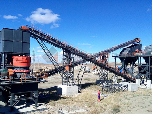
Primary Dump Hopper: Large blasted rock is dumped by haul trucks into a robust, reinforced concrete or steel hopper. Capacity is designed to buffer surges in truck deliveries.
Vibrating Grizzly Feeder (VGF): Positioned below the hopper. Its primary functions are:
Regulated Feed: Controls the rate of material entering the primary crusher, preventing overload.
Scalping: Removes fine material (often undersized for primary crushing or soil) through its grizzly bars (typically spaced 4-6 inches / 100-150mm apart). This bypasses the primary crusher, improving efficiency and reducing wear.
Protection: Removes very large, non-crushable debris ("tramp metal" can be handled later).
2. Primary Crushing (Coarse Reduction):
Primary Crusher: Receives scalped feed from the VGF. For a 400 TPH plant handling hard rock:
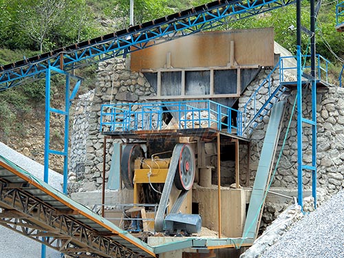
Jaw Crusher: Common choice for its robustness and ability to handle large feed sizes. A large jaw crusher (e.g., 60" x 89" or similar) with appropriate power is typical.
(Alternative: Gyratory Crusher): Offers higher capacity potential in a single unit but often has higher capital cost.
Function: Reduces rock from ~1m down to roughly 6-8 inches (150-200mm).
3. Secondary Crushing & Screening Loop:
Conveyor (C1): Transports primary crushed material