Diagrama do britador de mandíbula


Decoding Efficiency: A Comprehensive Guide to Jaw Crusher Diagrams
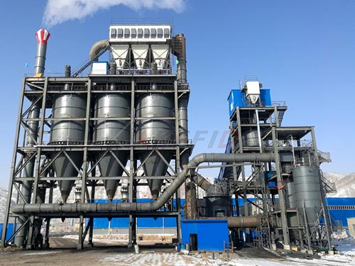
Jaw crushers stand as fundamental workhorses within the crushing circuits of mining operations, aggregate production plants, and recycling facilities worldwide. Their robust design and relatively simple operating principle belie the intricate interplay of components working in unison to reduce large rocks into smaller gravels or aggregates. Understanding a jaw crusher diagram is paramount not only for operators seeking optimal performance but also for maintenance personnel ensuring longevity and safety engineers mitigating risks. This article delves deep into the anatomy depicted in these diagrams, explaining each critical component and its role within the crushing process.
A função central: Esmagamento por compressão
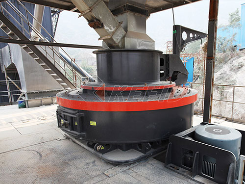
No seu coração, a jaw crusher operates on the principle of compressive force. Two vertical jaws form a V-shaped chamber called the crushing chamber. Uma mandíbula está parada (mandíbula fixa), firmly anchored to the crusher frame. The opposite jaw (mandíbula móvel) moves in an elliptical motion relative to the fixed jaw due to an eccentric shaft mechanism. As material enters from above (a abertura de alimentação), it falls into this narrowing chamber. The approaching motion of the movable jaw exerts immense pressure on the rock trapped between them.
This compressive action fractures larger rocks along their natural lines of weakness until fragments become small enough to escape through the narrowest point at the bottom of this V-shaped chamber – known as the Closed Side Setting (CSS) or discharge opening. The size of this CSS directly determines the maximum product size output by the crusher.
Deconstructing the Jaw Crusher Diagram: Componentes
A typical jaw crusher diagram meticulously illustrates several interconnected systems:
1. Quadro & Structural Components:
Quadro Principal: Provides structural rigidity and houses all other components under significant stress loads during operation.
Fixed Jaw Die Holder: A robust section integrated into or bolted onto one side of the frame where wear-resistant liners are mounted.
Forros laterais / Placas de bochecha: Wear plates bolted onto both sides of the frame interior adjacent to where material flows down from feed opening towards discharge opening preventing excessive wear on main frame walls itself
Volantes: Large heavy wheels mounted at both ends outside mainframe connected directly onto eccentric shaft providing inertia helping smooth out pulsations caused by cyclic nature crushing stroke maintaining consistent momentum especially during startup under load conditions
2. Câmara de esmagamento & Peças de desgaste:
Matriz de mandíbula fixa / Plate: Aço com alto teor de manganês