Procedure For Crushing Concrete Cubes


Procedure For Crushing Concrete Cubes: Ensuring Accurate Compressive Strength Results
Introduction
The compressive strength test of concrete cubes is arguably the most fundamental and widely performed quality control procedure in the construction industry. It provides a direct measure of the concrete's ability to withstand structural loads and is crucial for verifying compliance with design specifications and relevant standards (e.g., ASTM C39/C39M, BS EN 12390-3, IS 516). The crushing stage itself is critical; improper execution can lead to inaccurate results, potentially masking substandard concrete or falsely condemning acceptable material. This article outlines a detailed procedure for crushing concrete cubes accurately and safely.
Purpose
To determine the ultimate compressive strength of hardened concrete by applying a continuously increasing axial load to standard cured cube specimens until failure occurs under controlled conditions.
Principles
1. Controlled Loading: Load must be applied smoothly and continuously at a specified rate until failure.
2. Concentric Loading: The load must be applied centrally along the axis of the cube to avoid eccentricity-induced bending stresses.
3. Plane Parallelism: The bearing surfaces of both the testing machine platens and the cube faces must be parallel to ensure uniform stress distribution.
4. Correct Orientation: Cubes are typically tested on their casting side (not trowelled side) unless specified otherwise by standards.
Materials & Equipment
1. Cured Concrete Cubes: Standard cubes (usually 150mm or 100mm side) cured under controlled conditions (water tank at specified temperature) until testing age (commonly 7 days and/or 28 days).
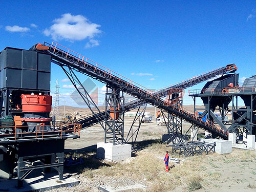
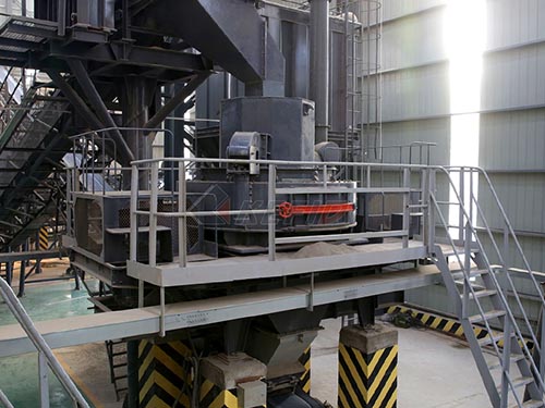
2. Compression Testing Machine (CTM): A calibrated hydraulic or servo-electric machine with sufficient capacity (typically >2000 kN for 150mm cubes), capable of applying load at a controlled rate (± tolerance as per standard). Must have valid calibration certificate.
3. Spherical Seat / Upper Bearing Block: A pivoting upper platen assembly to accommodate minor deviations in cube parallelism and ensure concentric loading.
4. Lower Platen: Fixed rigid plate forming the base.
5. Steel Bearing Plates / Auxiliary Platens: Hardened steel plates placed between the CTM platens and the concrete cube if required by standard or machine configuration to distribute load evenly and protect machine surfaces.
6. Cleaning Tools: Wire brush, cloths.
7. Personal Protective Equipment (PPE): Safety glasses/g