Crushers And Screens Drawing


The Critical Role of Engineering Drawings in Crusher and Screen Systems
Within the demanding world of mineral processing, aggregate production, and recycling, crushers and screens form the fundamental backbone of material size reduction and classification. While the physical machinery commands attention on site, the intricate engineering drawings governing their design, manufacture, installation, and maintenance are the indispensable blueprints for success. These drawings transcend simple sketches; they are comprehensive technical documents encoding vital information crucial for every stage of a crushing and screening plant's lifecycle.
1. The Foundation: Design Intent & Precision Specification
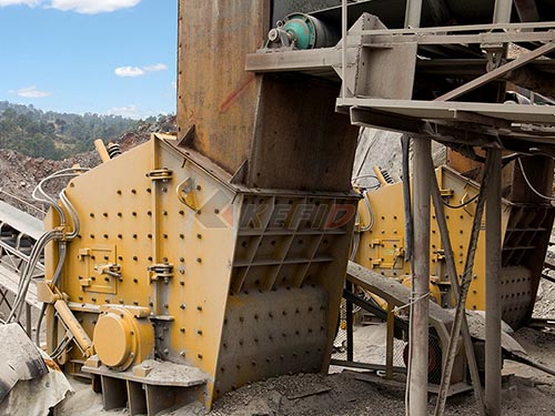
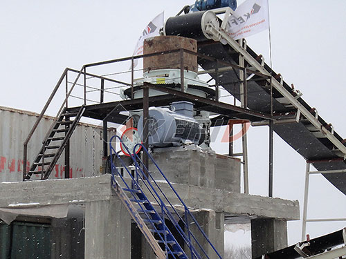
At the outset, detailed drawings capture the precise design intent of crushers (jaw, cone, impact, gyratory) and screens (vibrating, trommel, static grizzlies). They meticulously define:
Geometry & Dimensions: Exact sizes, shapes, tolerances for every component – from massive main frames and crushing chambers to individual shafts, bearings, screen decks, and mesh panels. This precision ensures parts fit together flawlessly.
Material Specifications: Critical selection of alloys for wear parts (mantles, concaves, jaw dies, screen media), structural steel grades for frames and housings, and specifications for seals and other components based on required strength, abrasion resistance, and environmental factors.
Assembly Relationships: Clear depiction of how hundreds or thousands of parts interrelate through exploded views, section cuts (especially vital for complex internal crusher mechanisms), and assembly instructions. This is paramount for correct erection in often challenging field conditions.
Load Paths & Structural Integrity: Calculations translated into drawings showing reinforcement points, weld specifications (size, type), bolted connection details (bolt grades, torque values), ensuring the equipment can withstand immense operational stresses.
Critical Interfaces: Precise location of drive motor mounts (alignment is crucial!), feed chutes ensuring optimal material flow onto crushers/screens without spillage or wear hotspots), discharge conveyors interfaces.
2. From Blueprint to Reality: Manufacturing & Quality Control
Drawings are the absolute authority on the shop floor:
Machining & Fabrication: CNC programmers rely on CAD models derived from drawings. Fabricators use detailed part drawings with dimensions and tolerances to cut plate steel accurately. Welders follow specified weld symbols and procedures.
Procurement: Bill of Materials (BOMs) extracted directly from assembly drawings ensure all components – bearings rated for specific loads/speeds; correctly sized belts or couplings; specific grades of screen cloth