Ball Mill Exporters Samples


1. PAINPOINT DRIVEN OPENING
Are you managing grinding operations where inconsistent product fineness leads to downstream processing issues and product rejections? Are unscheduled maintenance stops for liner changes and bearing failures causing significant production downtime? Is your energy consumption per ton of processed material eroding your operational margins? These are not just operational hiccups; they are direct costs impacting your bottom line. How can you achieve a more consistent grind size, extend maintenance intervals, and reduce specific energy consumption? The answer lies in the engineering and design of your core grinding equipment.
2. PRODUCT OVERVIEW
A ball mill is a robust industrial grinder used to reduce ore, cement clinker, and other hard materials into fine powder. Its operation is based on impact and attrition: material is fed into a rotating cylinder (shell) partially filled with grinding media, typically steel or ceramic balls. As the shell rotates, the balls are lifted and then cascade onto the material, crushing and grinding it through repeated impact.
Key Operational Workflow:
1. Feed Introduction: Crushed raw material is continuously fed into the mill through a hollow trunnion at one end.
2. Grinding Action: The rotating shell lifts the grinding balls, which then fall onto the material bed, achieving size reduction through impact and friction.
3. Particle Transport: Ground material is carried by a continuous feed of new material or by air (in dry mills) or water (in wet mills) toward the discharge end.
4. Discharge & Classification: Processed material exits through a discharge grate, often proceeding to a classification system (e.g., cyclones) where oversize particles are returned for regrinding.
Application Scope: Ball mills are applied in mineral processing for ore beneficiation, in cement manufacturing for clinker grinding, and in various industries for pulverizing chemicals and pigments.
Limitations: They are less efficient for very hard or abrasive materials compared to some alternatives, can generate significant heat, and have higher energy consumption than more modern vertical roller mills for certain dry grinding applications.
3. CORE FEATURES
Advanced Liner System | Technical Basis: Highchrome alloy steel with engineered lifter profile | Operational Benefit: Reduces liner wear rate by up to 30%, extends service life, and maintains optimal ball charge trajectory | ROI Impact: Lower liner replacement costs and reduced downtime for maintenance
Girth Gear & Pinion Drive Alignment | Technical Basis: Laseraligned during assembly with precisionmachined gear teeth | Operational Benefit: Ensures smooth power transmission, minimizes vibration, and prevents premature gear tooth failure | ROI Impact: Higher operational availability and avoidance of costly drive train rebuilds
Hydrodynamic Bearing System | Technical Basis: Oillubricated trunnion bearings with forced circulation cooling | Operational Benefit: Supports high mill loads with minimal friction, eliminates risk of bearing seizure under heavy load | ROI Impact: Proven reliability over decades of operation with predictable maintenance schedules
Variable Frequency Drive (VFD) Control | Technical Basis: AC motor controlled by solidstate frequency converter | Operational Benefit: Allows softstarting to reduce mechanical stress on drive components and enables speed optimization for different feed materials | ROI Impact: Lower peak power demand (reducing utility costs) and extended mechanical component life
Automated Lubrication System | Technical Basis: Centralized programmable grease/oil dispensing to all critical points | Operational Benefit: Ensures consistent lubrication without manual intervention, preventing failures due to missed lubrication events | ROI Impact: Reduced bearingrelated failures and lower labor costs for routine maintenance
Discharge Diaphragm Design | Technical Basis: Slotted grate design optimized for slurry flow or air venting in dry mills | Operational Benefit: Prevents ball discharge while ensuring efficient removal of ground product to avoid overgrinding | ROI Impact: Maximizes throughput capacity and improves overall grinding circuit efficiency
4. COMPETITIVE ADVANTAGES
| Performance Metric | Industry Standard Ball Mill | Our Ball Mill Solution | Advantage (% Improvement) |
| : | : | : | : |
| Specific Energy Consumption (kWh/t) | Baseline (100%)| Optimized drive & liner design reduces consumption| 510% reduction documented |
| Liner Service Life (months) Varies by application| Baseline (100%)| Highchrome alloy & profile engineering extends life| 2030% increase typical |
| Mean Time Between Failure (MTBF) Drive Train| 24 months| Precision alignment & lubrication increases MTBF| Up to 40% improvement |
| Grind Size Consistency (±% target)| ±10% from target P80| Stable charge motion & controlled feed improves consistency| Variability reduced by ~50% |
5. TECHNICAL SPECIFICATIONS
Capacity Range: From laboratoryscale 0.5ton batches to industrial mills exceeding 15,000 HP processing over 1,000 tons per hour.
Power Requirements: Dependent on size; large industrial mills typically require highvoltage supply (e.g., 6.6 kV or 11 kV) with dedicated substation support.
Material Specifications: Shell constructed from welded rolled steel plate; liners available in manganese steel, highchrome cast iron, or rubber; grinding media in forged/highcarbon steel or ceramic.
Physical Dimensions: Industrial mills range from ~3m diameter x 4m length up to >8m diameter x >15m length.
Environmental Operating Range: Designed for ambient temperatures from 20°C to +50°C; can be equipped with bearing cooling systems for hot climate operations.
6. APPLICATION SCENARIOS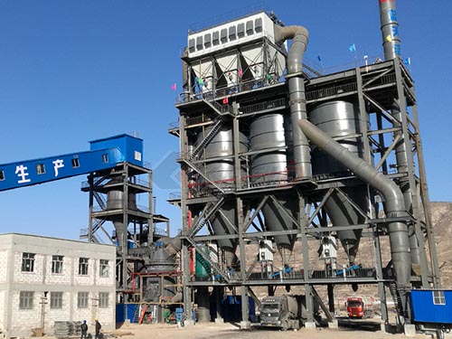
Copper Concentrator Plant Expansion
Challenge: A plant expansion required higher throughput but was constrained by existing grinding circuit capacity and high energy costs per ton.
Solution: Installation of two largediameter overflow discharge ball mills with highefficiency drives as secondary grinders.
Results: Circuit capacity increased by 35%, while specific energy consumption was reduced by 8%. The consistent grind output improved flotation recovery rates by an estimated 2%.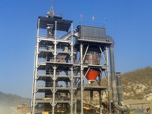
Cement Plant Clinker Grinding
Challenge: Frequent diaphragm clogging and high vibration levels in an older twocompartment cement ball mill were causing unplanned stops every 68 weeks.
Solution: Retrofit with a customdesigned composite diaphragm system and a full laser realignment of the girth gear drive train.
Results: Vibration levels dropped by 70%. Operational runs between planned maintenance intervals extended to over 6 months, directly increasing annual production volume.
7. COMMERCIAL CONSIDERATIONS
Ball mill procurement is a capital project structured around core specifications.
Pricing Tiers: Pricing scales primarily with power rating (HP/kW) and material specification. A standard configuration mill represents the base investment.
Optional Features: Key upgrades include advanced condition monitoring sensors (vibration, temperature), integrated control systems for feed optimization, specialized liner materials for corrosive applications, and comprehensive spare parts packages.
Service Packages: Suppliers typically offer installation supervision commissioning services annual inspection contractsand technical trainingfor plant personnel
Financing Options For large projects OEMs or their partners often provide access to equipment leasing structuresor project financing solutions spreadingthe capital outlay overthe equipments operational life
8. FAQ
Q1: Is your ball mill compatible with our existing classification circuit cyclones or separators?
Field data shows that providing detailed P80 feedand product sizerequirements alongwith slurry density data allows our engineers to model compatibilityand recommend any necessary adjustmentsfor optimal closedcircuit performance
Q2:What is the expected impact on our overall plant power load?
A detailed engineering review will specifythe total connected loadand starting current Our VFD option significantly reducesinrush current mitigatingthe impacton your plants electrical infrastructure
Q3:What are the standard commercial termsfor deliveryand payment?
Termsare typically FOB manufacturing plantor CIF named portwith apayment structure split acrossan advance payment milestone payments duringmanufactureand final payment uponshipment
Q4:What trainingis providedfor our operationsand maintenance teams?
We provide comprehensive operational manualsand recommend onsite trainingduring commissioning covering safe operation routine maintenance proceduresand basic troubleshooting
Q5:What isthe lead timefrom orderto deliveryfor alarge industrial ball mill?
For custom engineeredlarge mills lead times typically range from9to14 months dependingon current manufacturing capacityand thematerial specifications Standardized smaller modelsmay have shorterlead times